1. Chapter 1: FLO-2D Installation and Getting Started
1.1. General
Use this document to help create the FLO-2D input data and review the output data. It has chapters on getting started, resources, preprocessor programs, data files, output files, post-processor programs and troubleshooting. Chapter 4 is useful when learning to build data files. It breaks down each data file into a set of variables and gives a definition and instructional comments for the data files.
FLO-2D is recommended for use with Windows 10 or higher with 64-Bit operating systems, multiple processors and steady state hard drives. To generate and edit the data files, the QGIS/FLO-2D Plugin is used. QGIS facilitates assigning spatially variable data that can be interpolated from shape files, points and rasters. PROFILES is used to edit channel geometry data. Data files can also be edited using an ASCII text editor such as UltraEdit© or NotePad++©.
1.2. FLO-2D Installation
The FLO-2D Pro model is compiled for 64-bit, multi-core computers and cannot be run on a 32-bit system. The recommended minimum system requirement is 8 GB of RAM.
To install FLO-2D Pro, unzip the installation package and double-click FLO-2D-PRO-Setup.exe. Follow the installation prompts as they appear on the screen. By default, the software is installed in:
C:\Program Files (x86)\FLO-2D Pro
The FLO-2D model and processor programs are installed in the FLO-2D Pro directory. Supporting resource files are installed in the FLO-2D Documentation folder located at:
C:\Users\Public\Public Documents\FLO-2D Pro Documentation
The documentation folder contains user manuals, example projects, lessons, PowerPoint presentations, and other instructional materials.
1.3. Un-installing the FLO-2D Software
Remove the FLO-2D program and all of its attendant software from the computer with the Windows system Add Remove Programs tool. When removing the model, if the option appears to keep shared DLL/OCX files, do not remove them from the computer. To completely remove the FLO-2D files, delete the FLO-2D Pro Folder from the Program Files (x86).
1.4. Getting Started
Updates
When starting a new FLO-2D project, first visit the Sharefile FTP and download any executable updates. New features are frequently added to the model. Do not hesitate to notify FLO-2D Staff of any apparent programming bugs or problems that are encountered. These will be addressed as soon as possible. Program revisions are listed in the FLO-2D Pro Model Revisions document. C:\Users\Public\Documents\FLO-2D PRO Documentation\flo_help\Handouts.
Tutorials and Lessons
Tutorials and training videos are available for the FLO-2D Plugin. The Plugin is the recommended data editor.
Seeking Assistance – Technical Support
For technical support questions, please email FLO-2D via this Contact Form.
If there is a specific problem that needs to be resolved, zip the data files (only the *.DAT files, no output files *.OUT) and attach them to the e-mail along with a brief description of the problem and the project. Before sending the files, try to reduce the problem to its simplest form by turning off all components that are not contributing to the problem. For example, if the problem involves channel volume conservation, turn off the streets, buildings and levees and run the simulation again to determine if the problem still persists. Try to identify when the problem is first observed during the simulation (review SUMMARY.OUT) so that it is not necessary to run the entire simulation.
Questions regarding a project application are considered to be technical consulting and outside the scope of data input technical support. If assistance is needed on a project, reasonable consulting fees can be discussed to provide guidance and oversight.
Hydrology, Base Mapping and DTM Points
DTM data
To start a FLO-2D model, define the project area and compile available mapping, imagery and digital terrain model (DTM) data which might consist of LiDAR data, point shape files, rasters, contour maps or digital elevation model DEM data. The imagery and DTM points must have the same coordinate system. The most common formats for digital imagery are; *.tif, *.sid and *.jpg files
Note
Images must have corresponding world files (e.g. *.tfw, *.sdw and *.jgw).
If photogrametric or LiDAR data are not available, DEM data can be used.
Elevation data formats that are accepted by the QGIS/FLO-2D Plugin are ASCII Grid, ASCII xyz data sets and ArcGIS elevation shapefiles and Elevation Raster GeoTiff files.
Hydrologic data
Hydrologic data for a flood simulation can include both rainfall and discharge hydrographs. The rainfall runoff from a watershed model can be the desired product or the watershed model can be used to generate inflow flood hydrographs for downstream flood routing. In either case the hydrologic data should be carefully reviewed because the area of inundation is determined by the flood and rainfall volume.
Floodplain and channel detail
If river channels, bridges, culverts, buildings and streets are to be simulated, the user must be able to locate these features with respect to individual grid elements. Aerial imagery and shapefiles are used for this purpose. Additional data may be required for these components including bridge and culvert rating curves or tables, streets width and curb height, and river cross-section surveys.
Estimate the Project Area
To create a computationally efficient model, it is best to minimize the grid system around the project area. The project computational domain (or grid system) can be outlined using the aerial photography. The grid system boundary should be located so that the project area it is not affected by either inflow or outflow conditions. The inflow and outflow nodes should be considered as non-essential nodes (sources and sinks) and these should be located away from the project area.
If the project area is relatively small compared to the entire hydrologic basin that may need to be modeled, more than one FLO-2D simulation could be considered. A coarse grid system can be established for watershed or river system and a more detailed grid system created for the local project area where flood detail may be important. The outflow from the course grid system will constitute the inflow to the detailed grid system.
Selecting the Grid Element Size
See the FLO-2D Reference Manual for more instructions. Once the overall project area has been identified, estimate the grid system size (as a rough rectangle) and determine the approximate number of grid elements that would be required for different size square grid elements such as 50 ft, 100 ft, 200 ft, etc. The grid element size will control how fast the FLO-2D flood simulation will run.
To help with the grid element size selection, the following criteria are suggested based on a rough estimate of peak discharge. The peak discharge Qpeak divided by the surface area of the grid element Asurf should be in the range:
Qpeak/Asurf < 10.0 cfs/ft2 or in metric:
Qpeak/Asurf < 0.3 cms/m2
The closer Qpeak/Asurf is to 3.0 cfs/ft2 (0.1 cms/m2), the faster the model will run. If the Qpeak/Asurf is much greater than 10.0 cfs/ft2 or 0.3 cms/m2, the model will run more slowly (See table 1.1). After the grid element size has been selected, proceed with establishing the grid system using the QGIS/FLO-2D Plugin. There are QGIS workshop lessons to assist in getting started on a new project.
Table 1.1. Grid System Size.
Number of Grid Elements |
Model Simulation Speed |
|---|---|
< 50,000 |
Fast (minutes) |
50,000 – 250,000 |
Moderate (<12 hours) |
250,000 – 1,000,000 |
Slow (> 12 hours) |
1,000,000 |
Very Slow (> 1 day) |
Start Simple, then Add Detail
The first flood simulation for any project will be a simple overland flow model upon which a more detailed flood simulation will be built.
A suggested order of component construction is as follows:
Rainfall/Infiltration
Channels
Levees
Streets
Buildings
Hydraulic Structures (culverts, weirs and bridges)
Storm Drains
Multiple Channel (rills and gullies)
Mud and debris flows/sediment transport
As new components are added to a model and tested, other components switches can be turned off in the CONT.DAT file.
FLO-2D routes flows in eight directions as shown in figure 1.1 below.
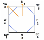
Figure 1.1. Flow directions.
The four compass directions are numbered 1 to 4 and the four diagonal directions are numbered 5 to 8. Some components such as levees are placed on boundaries of the grid element. The grid element boundaries constitute an octagon for components associated with the boundary.
Saving Data
When creating or editing the data files, it is suggested that the data files saved frequently and that one folder for testing a project and another one for editing a project. It is suggested that the data files be saved after finishing each component.
Develop the Project Files
Create a Project Folder
Start by creating a subdirectory for the project data files and import the DTM data base files, map images and aerial photos.
Build the Project Files
Use the QGIS/FLO-2D Plugin to graphically create and edit the grid system Follow the QGIS Lesson 1 “Getting Started” lesson.
Run the FLO-2D model
The required data files for a basic overland flood model are:
FPLAIN.DAT
CADPTS.DAT
CONT.DAT
TOLER.DAT
INFLOW.DAT
OUTFLOW.DAT
TOPO.DAT
MANNINGS_N.DAT
The INFLOW.DAT and OUTFLOW.DAT files are optional but are typically necessary for most applications.
Run a FLO-2D simulation by:
QGIS - click on ‘Run FLO-2D’ command in the File menu.
Copy the ‘FLOPRO.EXE’ file in the project folder and double click it.
Some General Guidelines
Data Input
When the data format appears confusing, review the data files provided in the Example Projects subdirectory of the FLO-2D folder using an ASCII editor such as NotePad++©.
File Management
The output files are always generated with the same name and will be over- written in subsequent model runs. To save any output files that could be overwritten, rename the file or create a new project folder, copy all the *.DAT files into it and then run the new flood simulation in that folder.
Graphics Mode
To view the floodwave progression during the simulation, run the simulation in graphics mode. This switch is set in the QGIS/FLO-2D Plugin by clicking the Control Variables button. Then check the Graphics Display mode and the Run button.
Things to check when creating the data files:
Grid System
The grid system should begin with grid element #1 and have no missing grid element numbers. There should be no dangling grid elements connected only by a diagonal.
Inflow/Outflow Nodes
Inflow and outflow nodes should not have other components assigned to them such as hydraulic structures, streets, ARF’s, etc. Outflow nodes should not be doubled up. Use a single line of outflow nodes.
1.5. Model Component Considerations
Channel Modeling
The 1-D channel component can simulate flow in channels defined by various geometries. The flow shares between the channel banks and the floodplain. Channels are defined in FLO-2D whenever 1-D flow is more accurate than overland flow. They can reduce flooding and help the water move downstream quicker than flow on the floodplain. An extensive Channel Guidelines document is available in the Manuals Folder.
Street Flow
Streets may convey or store only a small portion of the total flood volume, but may be important for distributing the flow to remote areas of the grid system. Street flow is simulated as a shallow rectangular channel with curbs. Street width and n-values are spatially variable. Streets are important to flood distribution in urban areas.
Levees, Dams and Breach
Levees and levee failure can be an important detail for floodplain projects. Levees are assigned to grid element boundaries with a crest elevations. Levee failure can include piping, overtopping and collapse. There is a levee and dam erosion component in FLO-2D. An extensive Levee, Dam, and Wall Breach document is available in the Manuals folder.
FLO-2D Levee, Dam and Wall Breach Guidelines
Rainfall and Infiltration on Alluvial Fans
Alluvial fan surfaces can be as large as the upstream watershed. Fan rainfall can contribute a volume of water on the same order of magnitude as the inflow flood hydrograph at the fan apex. Infiltration losses can also significantly effect flood- wave attenuation. Infiltration losses can be calibrated by adjusting the hydraulic conductivity. Spatial variable hydraulic conductivity can be assigned in the QGIS/ FLO-2D Plugin.
Sediment Bulking of Flood Hydrographs
An alluvial fan will have geomorphic features that identify the watershed potential for generating mudflows. For mudflow simulation, sediment concentration can be assigned in the INFLOW.DAT file. For desert alluvial fans with a sand bed, sediment concentrations in flood events can reach 15% by volume. For concentrations less than 20% by volume, the flow will behave like a water flood. The primary effect of increasing the sediment concentration, in this case, is to bulk the flow volume. Simulating Mudflow Guidelines is available in the Handouts folder.